Language: English











Strengthening of a Prestressed Concrete Multi-Girder Bridge
CFRP Laminate and U-wrap
CFRP upgrade of the precast girders — with the strengthening layout directly matching the simply supported force pattern: longitudinal carbon fiber plates for the mid-span flexural demand, end-zone U-wraps carbon fiber for the shear demand.

The project concerns an existing highway bridge in Spain, part of a twin-deck motorway with the parallel carriageway structure visible alongside. The superstructure consists of simply supported spans formed by closely spaced precast prestressed concrete I-girders topped with a cast-in-place reinforced concrete slab; each girder bears independently on reinforced concrete wall abutments and intermediate pier supports. This is the standard precast-prestressed bridge configuration built in large numbers across the Spanish motorway network during the 1980s and 1990s.
After decades of service, routine inspection and structural assessment found the girders operating below the capacity demanded by current traffic conditions. The abutment faces showed long-term water staining and efflorescence — evidence of age-related moisture exposure concentrated at the girder ends — and the load rating confirmed that both the mid-span flexural capacity of the girders and their shear capacity near the supports no longer met the requirements for present-day vehicle loads.
Rising traffic loads: vehicle weights and traffic volumes have increased well beyond the assumptions used when the bridge was designed, leaving little reserve capacity in the precast girders.
A simply supported system has no continuity reserve: unlike continuous decks, each span carries its own loads independently — flexural demand peaks at mid-span and shear demand peaks at the girder ends, with no redistribution possible between adjacent spans. Once either capacity is exceeded, there is no alternative load path.
Age-related deterioration: years of moisture exposure at the abutment zones degraded the concrete precisely where shear forces are highest.
Service continuity was non-negotiable: replacement or reconstruction was out of the question. The motorway could not tolerate closures, and any solution had to be executed entirely from beneath the deck.

CFRP upgrade of the precast girders — with the strengthening layout directly matching the simply supported force pattern: longitudinal carbon fiber plates for the mid-span flexural demand, end-zone U-wraps carbon fiber for the shear demand.

The project uses a combined CFRP system from Horse Construction, applied in two complementary stages:
1. CFRP plates on three girder faces — flexural strengthening
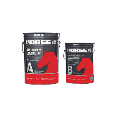
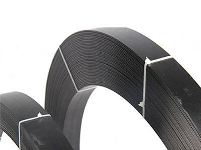
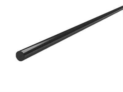
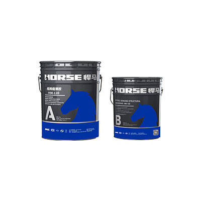
Pultruded carbon fiber plates were bonded with structural plate adhesive to three faces of every precast I-girder: the soffit (the tension zone under positive bending) and the lower portions of both webs, running longitudinally along the spans.
The soffit plates act as external tensile reinforcement: once bonded, they strain in compatibility with the concrete and internal prestressing steel, directly increasing the girder's positive-moment flexural capacity — the governing demand at mid-span of a simply supported span. The web-side plates enlarge the strengthened tensile zone and improve force transition around the soffit–web corners. Factory-pultruded plates were selected for their high, consistent fiber content, an important consideration for load-bearing bridge members where long-term performance depends on uniform material quality.


2. CFRP fabric U-wraps — shear strengthening and plate anchorage
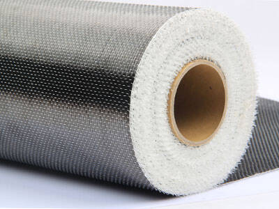
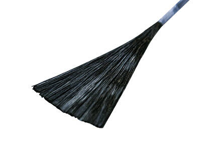
Over the bonded plates, unidirectional carbon fiber fabric (HM-30, 300 g/m², 0.167 mm cured thickness) was applied by wet lay-up as U-shaped wraps: the saturated fabric passes under the girder soffit and extends up both webs, forming a three-sided confinement band. Because the deck slab blocks full wrapping, the U-wrap is the standard shear configuration for this girder type.
The wraps serve two functions simultaneously:
Shear reinforcement — acting as external stirrups, the wraps intercept the diagonal principal-tension cracks that develop in the webs near the supports, raising the girder's shear capacity. The wraps are concentrated toward the abutment and pier regions, where shear demand in a simply supported span peaks — clearly visible in the denser strengthening coverage at the girder ends.
Mechanical anchorage of the plates — by clamping over the soffit and web plates, the U-wraps restrain plate-end and intermediate debonding, substantially improving the durability and safety margin of the flexural upgrade.


Substrate defects were repaired and leveled before bonding, corner fillets were applied at the web–soffit junctions to avoid stress concentration where the fabric bends, and temporary wedging held the fabric in place during resin cure to ensure full contact with the concrete.
The combined plate-and-U-wrap system restored both the flexural and shear capacity of the simply supported precast girders to meet current loading requirements, extending the service life of the bridge at a fraction of the cost and disruption of replacement.